- Share this article
- Share this article on Facebook
- Share this article on Twitter
- Share this article on LinkedIn
- Email this article to a friend
Feeding the Beast—Transferring Radio Frequency Energy from Your Transmitter to Your Antenna
Copyright 2018 by Don Keith
It occurs to me that we will soon have an influx of relatively new operators to the HF amateur radio bands, newcomers who may or may not have experience with or knowledge of the compromises involved with building antenna systems. They may try to get by cheaply and quickly, just to get a taste of the new spectrum now available to them. And in the process, they may have a less than satisfying experience.
I won’t attempt to even delve into the antennas themselves. There are myriad sources for information, including books like the ARRL Antenna Handbook and in discussion forums on sites like eHam.net and QRZ.com. An especially good discussion of simple antennas is available on the excellent website of L. E. Cebik, W4RNL, located here. Mr. Cebik also has an interesting three-part discussion of the popular G5RV antenna, which allows use on several amateur bands, and you can see the first article by clicking here. For a complete list of antenna topics from W4RNL, click here.
I would recommend to any newcomer that he or she learn along the way but keep it simple in the beginning. By all means, get an antenna up so you can be on the air, joining in on the fun! But for the time being, avoid phased arrays, delta loops, and exotic hunks of metal in the sky. For the moment, stick with dipoles, verticals, or simple loops. They are easier to play with and you might learn something from installing them. Remember, making mistakes is one of the most effective ways of learning, too. If you purchase commercially made antennas, be sure to follow the manufacturer’s directions closely, including recommendations for properly getting the RF from your radio/amplifier to the antenna itself.
And that will be the subject of this article—the feeding of your antenna…getting as much radio-frequency energy from the transmitter to the antenna as possible, and trying to make sure as much of the precious RF is emitted into space so someone halfway around the world can hear you. There are several potential combinations of feed systems and matching units that are commonly used by amateurs. For our purposes, we will consider the following simpler and more typical ones:
--Coaxial cable with no matching unit except what might be internal to the transmitter
--Coaxial cable with an external outboard matching unit
--Open wire or ladder line with or without an external outboard matching unit
Wait, what is this “matching unit” stuff? You mean a “tuner?” Actually, an antenna tuner is a matching unit, and one quite often employed by hams, but there are other means and devices for matching rigs to antennas that are not “tuners.” These devices are technically a part of the antenna system (so are the antenna, the dirt beneath it, the trees in the area, your kid’s bicycle propped against your vertical, the mountain fifteen miles away, and the ionosphere miles above our heads, but we don’t have control over most of that stuff). Matching units allow the operator to vary the capacitive and inductive reactance seen by the transmitter in order to get a better “match,” to allow as much of the radio frequency energy coming from the transmitter to be transferred to the antenna and into the air as possible.
Let’s talk “matching” for a moment. Most transmitters and outboard amplifiers today are designed to work best when they are outputting radio frequency into an impedance of 50 ohms. The operator has very little control over the load impedance of the typical transistorized transceiver today, and not much more control over the output impedance matching of a common outboard amplifier. However, the impedance presented by different antenna systems at different frequencies can vary widely and the operator may need to dramatically vary the reactance values the transmitter encounters in order to try to get a better transfer of power to the feedline first, and possibly to the antenna itself. There are other matching devices, such as baluns (“balanced—unbalanced transformers”), mechanical devices like so-called gamma matches at the antenna feed point, and even relays that switch in and out all sorts of odd components in what is sometimes a Rube Goldberg-type setup. For the purpose of this article, let’s consider the matching unit to be either an antenna matching device internal to your radio or a similar external device, either of which is typically called an “antenna tuner.” (I quibble here because we are not actually “tuning” the antenna. We are attempting to get the output circuit of the transmitter into synch with the impedance of the feed line and/or the antenna and everything else that makes up the “antenna system.”)
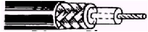
Typical coaxial cable--an inner conductor, plastic dielectric, woven shield, and plastic covering.
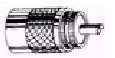
Screw-on coax connector, PL259-type.
Coaxial cable, or simply “coax,” is a very popular means of getting radio frequency energy from transmitter to antenna. The more popular types are already designed to offer 50 ohms impedance (or relatively close), are easy to work with, can be run in close proximity to other cables, tower legs, or metal objects, and use simple connectors that can be securely attached to the transmitter and the antenna. Coax is a good choice for an antenna such as a dipole that is designed to be used on only one operating band (or odd multiple harmonics of that band). Such an antenna, properly constructed and cut close to the preferred operating frequency so as to be in reasonable resonance, will show impedance close enough to 50 ohms that your feedline and your transmitter output circuit will be happy and everything will be in harmony. The maximum amount of energy possible will be moved from transmitter to feed line to antenna and emitted into space.
But what about very broad amateur bands, like 75/80 meters, or those bands that require more antenna-per-hertz, like 160? It is asking a lot of a piece of wire and its feedline to be close to resonant across such a wide band. Even if the wire is cut for the middle of the band, it may be considerably out of resonance—offering impedance that is a long way removed from 50 ohms—when you try to use it at the extreme ends of the band. This creates the phenomenon we call “standing waves.” Simply put, standing waves are currents that are reflected—due to a mismatch—back from the feed point of the antenna, returning back down the feedline toward the transmitter. SWR—or “standing wave ratio”—is a way of expressing the amount of your outgoing power that is getting reflected back down the feedline. (This is a rather simplistic description of a decidedly complicated thing that is going on, but I believe it is accurate and will suffice for this discussion.)
Let me state here that achieving a low SWR is not a bad thing, though it is not necessarily a critical one. But I thought SWR was evil incarnate! Don’t all the manuals for my rig scream about getting the SWR to 1.5-to-1? Won’t it burn up my radio before the credit card bill even shows up? Isn’t all that power that gets sent back in the direction of the shack wasted? And isn’t it wasted in the form of heat? Am I not charged to get no worse than a 1-to-1 match or they’ll revoke my license?
Not necessarily. The RF energy does not necessarily go back into your radio or get burned up in the feedline. A portion of it is simply sent right back up the feedline each time it is reflected down it—traveling at the speed of light. If the feedline has relatively low loss, you really don’t lose much of the RF at all. Most of it is eventually sent out into the ether by the antenna. The fact that some of it made a lot of trips up and down the feedline before it was emitted into space is immaterial. Granted, a very large SWR does cause enough heat, even in the lowest loss feedline. It can cause damage to the cable and anything close to it. That is why most modern radios employ a circuit that cuts back power and eventually ceases operating if presented with a severe mismatch at the antenna output circuit.
Now, how does this apply to that nice, easy-to-use coax? Compared to some possible transmission lines, a good quality coaxial cable is relatively low loss. But as the type you use gets smaller, as the frequency on which you plan to use it gets higher, as the length of cable you have to use to run from your rig to the antenna gets longer, and as the type of dielectric (the stuff that separates the two conductors inside the cable) changes, the amount of signal you lose in the wire goes up, up, up. If you are feeding an antenna that is close to 50 ohms, using transmission line that is near 50 ohms, and operating close to the antenna’s resonant frequency, you should not have a real problem. If you have fairly good coax and, if operating on the HF bands, a run of less than 200 feet or so, and your antenna is resonant for the frequency you are transmitting on, you will do fine. But if the load is mismatched at the antenna, if you are seeing a higher amount of reflected power, you may be losing more precious signal than you thought. And that could explain why nobody answers your calls or when you do make a contact, they tell you that you are “down in the mud.”.
Here’s what is happening. Let’s say you lose 20% of your 100 watts of output power because of natural loss in the coax cable as the RF energy is making its way up to the antenna. And let’s say you have a high SWR because you are attempting to operate the antenna system a long way out of resonance, or because the antenna is not designed to be used on the band you are using. To keep the math simple, let’s say that 30% of your original RF is be getting shoved back down the cable in the form of standing waves. Well, you lose 20% of that as it goes back toward the transmitter, too, because you have the same natural loss in the cable going that way as you did going toward the antenna. You have now lost half your original power, and what’s left still of the original RF energy will dutifully go right back up the feedline again! It loses 20% more, warming up your coax nicely. And once again, 30% of that quickly diminishing power that reaches the feed point gets reflected yet again, right back down the line, and gets another 20% of it carved away by the loss of the cable. As you see, the power is waning quickly!
Again, for a number of reasons, coax is an excellent choice as a feedline for most antennas, and especially dipoles and beams. It is almost—in forms that have even less loss at those frequencies—the exclusive choice at VHF and UHF. But there is one very important caveat: coax is best used when feeding a resonant or close-to-resonant antenna. You may find that an antenna cut to the middle of a band will work just fine all the way across the band. That may be true, but don’t expect it to work much place else. There are an almost infinite number of frequencies in the amateur bands where you may want to transmit and receive in which an antenna will not be anywhere near resonant, and where that non-resonance will induce a honking big SWR.
Well, you say, there is a simple solution! All you have to do is use the tuner inside your radio, or break out the catalog and buy an outboard tuner that will match your output to much broader impedance loads. That way, you reason, you can use a single dipole on a bunch of ham bands because the tuner manufacturer says it will tune up a rig to about anything. You have seen the reviews of tuners that will match a transmitter and its coax to a set of box springs, a ten-penny nail, a linguini noodle.
Sorry, but that is not really the issue here. Yes, a good tuner can convince your rig that it is working into a nice, comfortable 50-ohm load, even if the antenna is ridiculously non-resonant and presents a very lopsided SWR, transferring all that power to the antenna and flinging it around the world. You can sit there and transmit all day, your transmitter running cool, not even threatening to shut down because of an excessive SWR. The meter on the tuner might say 1.2-to-1 or 1.3-to-1, so everything must be working great. Well, don’t kid yourself. All you have really done is lie to the transmitter output circuit, fooling it into trying to send all that RF into a badly mismatched antenna system. You have cranked in the correct ratio of capacitive and inductive reactance for both you and your radio to think everything is peachy. But remember, those unavoidable standing waves are still coursing up and down your feedline, maybe invisible to your radio and tuner meter, but that reflected and re-reflected power is growing fainter and fainter with every trip up or down the coax. And only a small amount of your transmitter power is actually being sent out into space to be detected by that DX station you keep trying to call.
So coax is not a good choice at all for using an antenna on multiple ham bands? It can be! First, if you learn some antenna theory, you will discover that some antennas, such as a dipole, are resonant on odd multiples of the lowest frequency band for which it was measured and cut. A closed loop is actually resonant on all multiple harmonics of the lowest frequency for which it was designed to be resonant. You can use coax and get some degree of resonance on several bands. But remember, if you cut a dipole for, say, 3.75 megahertz in the middle of the 75/80 meter band, it will really not be close to resonance in any other amateur band, except, in a stretch, 17 meters. If you play with the length, though, you might be able to move the range in somewhat and pick up some other bands, with an SWR that is not such a power killer and can be tamed by most internal tuners. Maybe not the best situation, but it might get you on the air on a few bands.
Don’t give up on the antenna tuner, either. While you are not solving the real problem by installing the tuner at the transmitter end of the feedline, you can, instead, put it near the antenna feed point so that you are actually tuning both transmitter and feedline to match the antenna. This eliminates a great deal of that bouncing SWR and its loss as it surges up and down the coax. Even if you put the tuner somewhere in the feedline rather than right at the feed point, you can eliminate a portion of the lossy coax, with the less amount of cable between the antenna and the tuner, the better.
There are a few problems with this plan, though. You need a tuner that is designed to be exposed to the elements if you have to put it outside, if there is not protective structure close enough to house it. If you try to put the unit at the feed point of the antenna—the most ideal place—you need some way to support its weight. And, in most cases, you need to get voltage to the tuner to operate its components remotely. I think you can see how that complicates the matter.
So, there is no such thing as an easy coax-fed antenna that can be used on more than one ham band? Or one that is resonant for the entire length of a particular band? Not true. There are several antenna choices that can help you solve the coax problem. You can research the fan dipole, for example, in which a single run of coax can be used to feed dipoles cut for several bands. Other antennas can be designed to be relatively broad-banded, such as the log periodic beam. And, the truth is, SWR is probably not a big problem on a well-designed dipole with good quality coax if you only intend to use it on a single band or odd multiple harmonics. Even the internal tuner in most rigs will easily allow you to overcome any resulting mismatch, and if the coax has relatively low loss and the run length of your feedline is not excessive, you probably will not lose an appreciable amount of power.
But suppose you want a single multi-band antenna. A good choice is a dipole, cut to be ½ wavelength long on the lowest band on which you want to use it, fed with open wire feedline, and fed with a matching unit or units. (The formula for determining the length of such a dipole is 468 divided by the frequency in megahertz—for 3.75 mHz, that would be just under 125 feet).
Open wire feedline? Isn’t that something your grandfather might have used? Actually, such feedline is enjoying something of a comeback. There are now ten amateur high-frequency bands, and in an effort to work as many of those bands as possible with as few antennas as necessary, resourceful hams have turned to…well…an oldie but goodie.
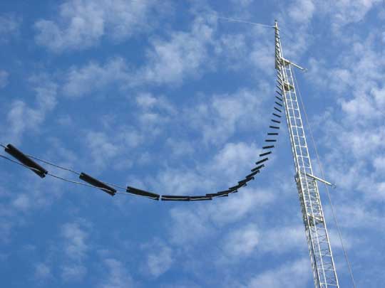
True ladder line, as constructed and sold by W7FG.
There are variations of this type transmission line, such as true air-dielectric open line, so-called twin lead like folks used to use for the TV antenna when folks had TV antennas, window line, and ladder line. Each name describes the type design of the feedline that keeps two conductors evenly separated from each other for the length of the line. The characteristic impedance of such feedline can range from 200 to over 600 ohms depending on several factors, such as the material used to space the two conductor wires apart and how far apart the wires are. But one thing is constant: the distance between the two conductors must remain the same for the entire length of the feedline or it begins to mess with the impedance of the line.
I know what you are thinking. If a dipole is in the neighborhood of 50 ohms already, then are we not introducing a serious mismatch by feeding it with some wires that may be 600 ohms? The simple truth is, it does not matter nearly as much as it does with coax. This type of transmission line has such low loss in a run of reasonable length that the standing waves on the line are eventually mostly radiated in the form of “good” RF, and those trips up and down the line are a relatively small factor.
There are ways to get the match closer before we depend on an antenna tuner—internal or external, at the rig end of the feedline or at the antenna feed point—to make the transmitter happy. Many hams use a current balun (remember, that is a balanced/unbalanced transformer) at some point in the ladder line to step the impedance down to something closer to 50 ohms. They hook the two conductors of the balanced line to one side of the balun and then run coax from the other side—the lower impedance side—to the transmitter. This also solves a rather knotty problem with open wire feed line. It is very susceptible to being affected by any nearby metal or cables. You should never run open wire feedlines down a tower leg, along a metal gutter, or adjacent to other cables or feedlines. This will almost certainly lead to problems tuning an antenna system that contains this type transmission line. Even trees or wet vegetation can alter the performance of air-dielectric feedline.
This is just one reason why many hams reject balanced transmission line. There is also the problem of attaching ladder line to your radio. You most likely have coax connectors on the rear panel of the rig. Many tuners also have only coax or single wire connectors. How in the world can you hook that stuff up to that nice screw-on connector on the back of the radio? Glue or duct tape are not the answers!
Once again, the answer is the balun. It may be external, outside somewhere, maybe at the feedpoint of the antenna, maybe somewhere in the line, maybe where the line needs to enter the shack. Then a short run of coax is used for entry into the house, next to those other cables, the gutters, and the air conditioner ducts. Or it may be right next to the rig with a short coax jumper to the antenna connection on the radio in order to avoid long runs of lossy coax. Or, more commonly, next to your antenna tuner, which will be necessary to tune to the broad impedance range the antenna will present as you move about the various ham bands. The balun could also be inside the antenna tuner if it has a “balanced” antenna connection.
A dipole fed with open wire line or one of its variations is, by definition, a “balanced” antenna. That type transmission line is called “balanced line.” They go together nicely. But the output circuit of your transmitter is most likely unbalanced. So is coax. So is the coax connector output of your tuner. Some tuners offer a balanced output, relying on a balun inside its case—typically a 4-to-1 type balun, changing the impedance, say, from 300 ohms at the antenna feed point to about 75 ohms on the other side of the device. But there are also special tuners designed to match the unbalanced 50-ohm transmitter output circuit to a balanced antenna system. There have been several articles in the various ham magazines about designing and constructing balanced tuners, and several manufacturers produce them as well.
Before the more convenient-to-use coax came along, amateurs almost all used open wire transmission lines, primarily because they were simple and could even be constructed using easy-to-locate and cheap materials. They weren’t as concerned as we are with the problems of matching their transmitter to antennas fed with ladder line. That was because the output circuits of transmitters in those days were much broader and adjustable. But the main reason was because the stuff worked very well and got more of the RF to the antenna and out into the ether.
Now, with little loading to be done internally to our solid state transceivers, we have, in effect, moved the matching circuit from inside the radio, out onto the desktop in the form of an “antenna tuner.” However, with the desire to use an antenna on a broader range of bands, and in an effort to get as much power to the antenna and have it radiated, ladder line and its cousins are making a respectable comeback. Several distributors sell such line at reasonable cost, and their web sites even offer interesting commentary on its use, selecting baluns, and the recommendations for physically and electrically connecting it to the antenna.
So there we have it, a look at the two primary types of antenna feedlines—coax and open wire—and the various ways of using it to achieve a better antenna system. Neither is a right or wrong choice, a better or worse one. As you will discover in our hobby, there are advantages to about any way of doing something, and there are disadvantages, too. And with antennas and feedlines, the truth is everything is a compromise, and there is no perfect system. But some are “more perfect” than others.
It can be a lot of fun, trying to devise ways to make those compromises as limited as you can, all in the quest for having that station on the other end of the QSO say, “You’re kidding! You’re not running 100 watts. You’re 20 over S9 here!”
Don Keith N4KC has been a ham radio operator for more than fifty years. After a long career in broadcasting and advertising, he now writes full time and has published more than thirty books, fiction and non-fiction, on a wide range of subjects including amateur radio. See www.donkeith.com or www.n4kc.com for more info.